Hacking the Heat: Retrofitting Adax Heaters with ESPHome and Custom PCBs
A multi-phase journey from cloud-dependent heating to fully local, custom-hardware control.
Winter in Sweden means heating is not optional. We have a set of Adax Neo heaters in the house. They are good-looking, slim panel heaters, and they even have "Wi-Fi." But like so many IoT devices today, that Wi-Fi meant relying on a proprietary app and a manufacturer's cloud.
I wanted more. I wanted local control in Home Assistant, faster response times, and I didn't want my heating to depend on an external internet connection.
What started as a simple software hack escalated into a full-blown custom hardware engineering project. Here is the story of how I took total control of my heating system.
Phase 1: The Software "Infiltration"
The first breakthrough was realizing that the "smart" module inside the Adax heater wasn't some mysterious black box. It was powered by a standard ESP32.
This changed everything. If it's an ESP32, it can run ESPHome.
I managed to flash a custom ESPHome firmware onto the existing Adax modules. Suddenly, my heaters weren't talking to a remote server; they were talking directly to my Home Assistant instance over the local network.
I spent some time fine-tuning the configuration, figuring out the correct current settings for the 800W and 1000W 400V variants, and optimizing the development workflow using the ESPHome CLI for rapid over-the-air updates.
At this point, I had achieved the original goal: local control. The heaters worked perfectly. I could have stopped here.
But I didn't.
Phase 2: The Hardware Itch
While the software solution was functional, a few things pushed me to take it to the next level:
Hardware Failure: One of my Adax heaters developed a broken control unit. Replacing that proprietary board is incredibly expensive, making a DIY fix financially viable.
Future Proofing: The stock ESP32s are fine for Wi-Fi, but the smart home world is moving toward Thread and Matter. I wanted hardware ready for that shift.
The "Because I Can" Factor: There is a specific kind of satisfaction in knowing you understand and control every single millimeter of your infrastructure.
I decided to ditch the original Adax control board entirely and build my own drop-in replacement.
Phase 3: Reverse Engineering and PCB Design
The goal was to create a board that fits perfectly into the existing slot on the heater and uses the exact same 6-pin connector.
The Detective Work
Using a multimeter on an unplugged board, I mapped out the 6-pin header connecting the control unit to the heating element. We found the essentials: 3.3V power, Ground, a GPIO for the relay, and an Analog pin for the temperature sensor (NTC). There was also a simple resistor on Pin 4 that acts as a hardware ID, telling the heater to accept external commands.
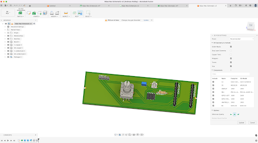
Entering the Matrix (Fusion 360)
Armed with the pinout, I moved into Autodesk Fusion 360 to design the physical board.
The Brain: Instead of soldering an ESP32 chip directly, I designed the board with female headers to accept a Waveshare ESP32-C3 Zero. This is crucial. It means today I use Wi-Fi, but tomorrow I can unplug it and drop in an ESP32-C6 to upgrade the heater to Thread and Matter without redesigning the main board.
The Interface: I added a standard EC11 rotary encoder for the dial and an I2C OLED screen to display temperature and status, mimicking the original functionality but with better hardware.
The Build: I stuck to through-hole components to keep the hand-soldering process easy and rugged.
The schematic looked like a spiderweb, but the logic was sound. I converted it to a PCB layout, defined the exact board shape — complete with the weird little notch on the left side — and added the ground planes.
Phase 4: Assembly and The Next Frontier
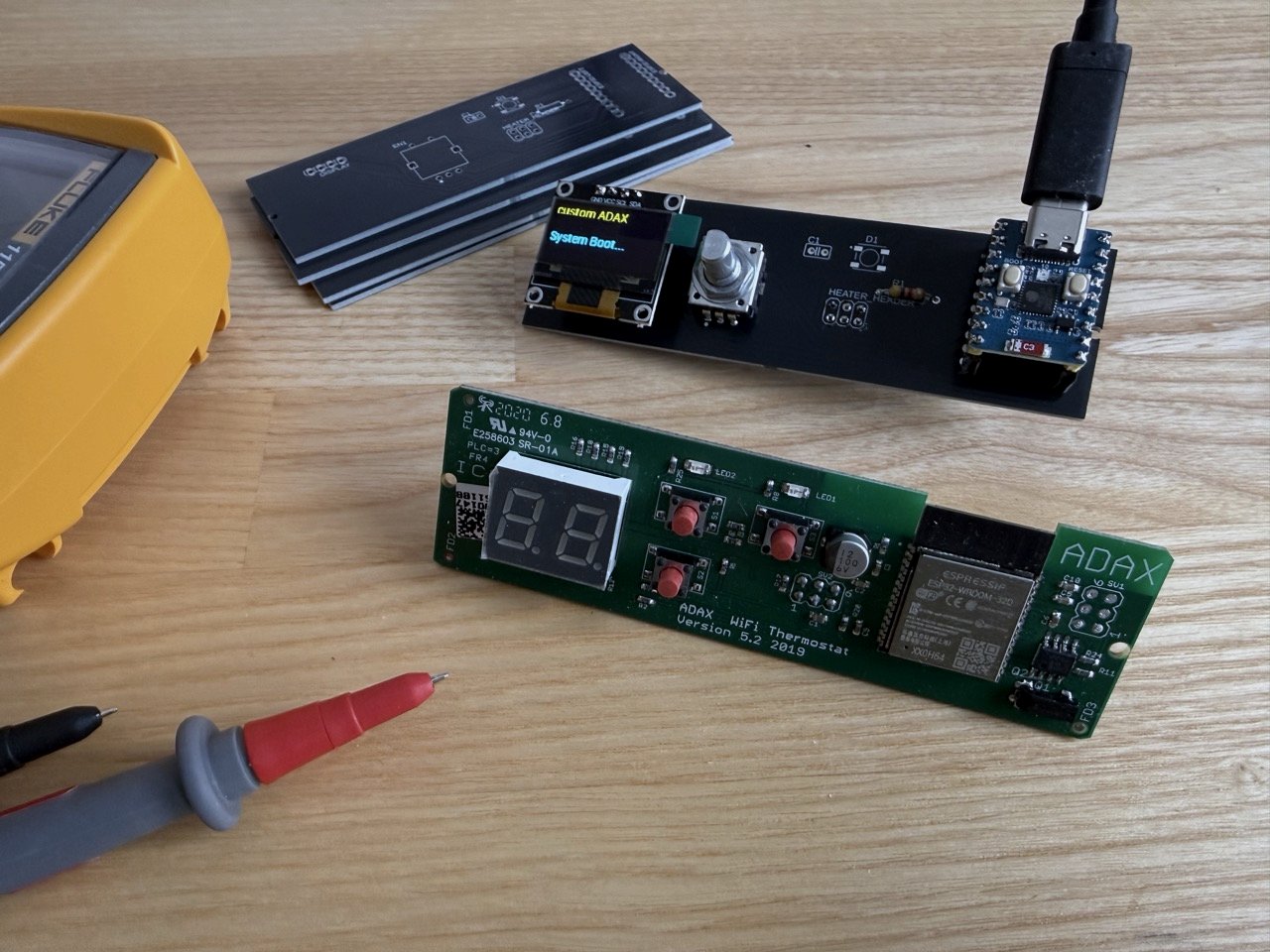
I exported the Gerbers and sent them off to a PCB manufacturer in China.
Opening that box to find professional, black PCBs that existed only on my screen two weeks ago was an incredible feeling. After a quick session with the soldering iron, the components were mounted.
I flashed my new ESPHome configuration, plugged the board into the heater, and the screen lit up. The prototype works beautifully. The relay clicks exactly when it should, and the rotary encoder is buttery smooth. Winter is coming, and this time, I'm completely in charge of the thermostat from the hardware all the way up to the server.
But a bare PCB with an exposed OLED screen isn't quite wife-approved yet.
Now that the electronics and software are locked in, the final step is physical: designing and 3D printing a custom housing. The goal is to create a sleek cover that mounts perfectly to the Adax chassis, giving the new screen and encoder knob a factory-finished look.
Stay tuned for the 3D modeling process!